Distortion isn’t something we like to see in a project – we work hard to avoid it and correct it when necessary. Sometimes, though, a project is set up for distortion during the design before it reaches our hands. In cases like this, we can retroactively address the problem, as highlighted in the example below. However, things (and welds) go much smoother when we are involved from the beginning as a strategic partner.
Customer and Industry
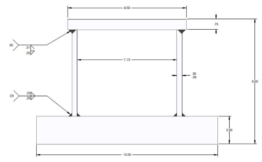
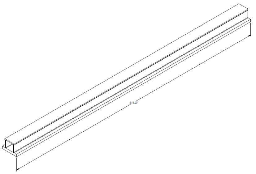
In a case study that is now a lesson for manufacturing and engineering students, a customer contracted ENI to fabricate a box section beam to be used in a cantilever configuration. The welding design called for an assembly that would be 215” long and made of HY-100 plates welded continuously along the full length at all four corners. The bottom welds were specified as .25” fillets inside and out of each vertical plate. The top welds were specified as .31” bevels with .25” reinforcing fillets from the outside. It is important to reiterate that ENI was not involved in early planning, and was given designs to follow for fabrication.
The Challenge
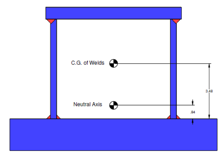
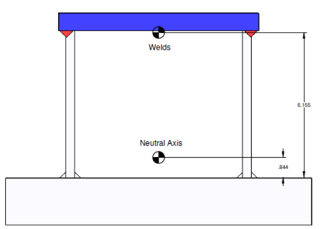
Although the weldment appeared to be manufacturable at first glance, a closer inspection revealed significant offset between the centroid of the welds (3.48") and the neutral axis of the beam (.84"). This difference creates upward bowing that leaves the top plate in compression and the bottom plate in tension. Formulaic calculations revealed total inherent distortion of .491".
These calculations were based on a theoretical approach to first tack together the entire assembly before making all welds simultaneously. That, however, wasn’t feasible due to required welding at two of the four internal corners.
In order to offset the metal's natural tendency to bow, the team explored alternative assembly sequences to make the impossible happen.
The Journey
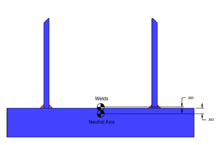
The first alternate assembly sequence called for bottom-up welding. The team started by calculating the distortion created by welding the two side plates to the bottom (.153"), and then by calculating the distortion created by welding the top plate to the side plates (.553"). The net sum was .706" — more distortion than the original baseline calculation.
The top welds resulted in distortion of .759". The bottom weld resulted in distortion of .062" in the opposite direction, for a net of .697". This reverse assembly resulted in distortion levels that were nearly identical to the first alternate sequence.
The team then calculated a third assembly sequence. The contract called for a pair of beams, so the team built them back-to-back with temporary welds bonding the two bottom plates. This created a plane of symmetry where the two bottom plates were joined together.
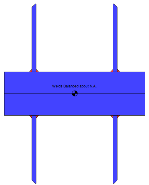
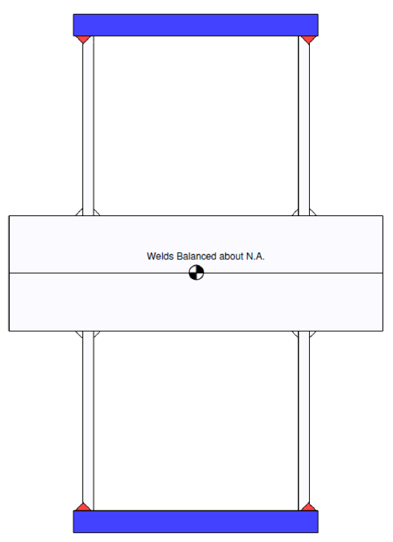
Since the welds were balanced around a neutral axis, no distortion occurred. The welding spec, however, prohibited stress relief, so when the pair of beams were separated, all residual weld stress was released at the same time, which created a stress condition similar to the baseline theoretical approach of all welds being made simultaneously, producing a distortion value of .491".
The Discovery
When the teams cut the two beams apart, the weldments bowed away from the plane of symmetry and a 1” gap opened up at each end. This means that each beam bowed .5" — the best possible distortion condition within the design limitations.
The Solution
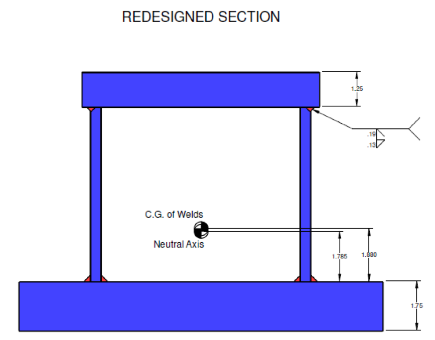
With each project, the team learns and grows. While they could not redesign the piece incorporated into this contract, the team used this as opportunity to outline what changes they would make – if they could. The solution required a change in the thickness of the plates and the size of the welds to get the center closer to the neutral axis.
The team determined that the appropriate course would have been to increase the thickness of the top plate from .75" to 1.25" and to decrease the thickness of the bottom from 2.00" to 1.75".
In addition, designers could have reduced weld size without compromising safety since longitudinal welds don’t transfer much load in a beam when it comes to bending. Instead, they only transfer shear.
This reduction in weld size would have dramatically reduced bowing and would therefore have made the design even more manufacturable.
The Results
The fabrication team did the best it could within the constraints of the design. Had they been included in the early planning stages, ENI could have identified the design's main sticking points and offered suggestions to make the beams more manufacturable.